|
Overview
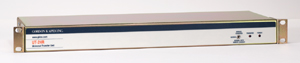
The UT-24R Universal
Transfer Unit is designed as a general-purpose switching device for use
with telephone, data, and low-power electrical signals. The unit is
arranged as 24 two-wire circuits. Each circuit has an input, a normal
output, and a transfer output. The two wires of each circuit are
designated as tip and ring, reflecting the telephony orientation of the
UT-24R.
UT-24R features include 24
circuits of transfer, two LED status indicators, a manual transfer
switch, an auxiliary relay contact, a return to normal mode delay timer,
and universal powering. Also included are provisions for a normally
open, normally closed, or logic level signal to control the operating
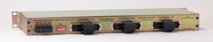
mode. The unit is completely self-contained in a cabinet that can either
be rack or wall mounted. Interconnections are made using standard
25-pair telephone-type plugs and a terminal strip. This method provides
simple, time-efficient installation and maintenance.
The UT-24R Universal
Transfer Unit is intended to serve as a useful “building block” for
special applications. Up to 24 two-wire input pairs can be switched
between the normal and transfer outputs. The switching is done
“metallically” using electromechanical relays. This method provides
excellent AC and DC isolation between connected and uncommitted
circuits.
A typical application
would be with two-wire telephone circuits. These circuits could include
loop start trunks, ground start trunks, auto ring-down circuits, and
private lines. Because the UT-24R is configured to transfer 24
independent pairs, four- and six-wire E&M circuits, four-wire leased
lines, and other special circuits can be connected.
Data lines that do not
require special shielding can be switched by the UT-24R. A prime example
would be 10-BaseT local area network cabling. A normal and emergency
routing scenario could be created, with the UT-24R providing the
switching.
The UT-24R can also be
considered as a giant A/B switch, with 48 individual inputs connecting
to 48 normal and transfer outputs. Low-power control signals can be
switched between normal and emergency equipment.
UT-24R Specifications
Transfer Circuits: 24, 2-wire (“tip and
ring”) pairs
Arrangement: each circuit has three pairs (six leads) associated with
it: an input pair, a normal pair, and a transfer pair
Switching Method: sealed bi-furcated electromechanical relays,
break-before-make
Contact Rating: 0.5 amperes maximum, 60 volts AC or DC (resistive)
Contact Input:
Compatibility: connected contact must be capable of handling 5
milliamperes at 40 volts DC; contact inputs on multiple UT-24R units can
be bridged (connected in parallel)
Operating Modes: switch selectable for normally open (not shorted) or
normally closed (shorted)
Logic Input:
Compatibility: connected signal must provide minimum logic high current
of 2 milliamperes. Logic input current is limited via a 1000 ohm
resistor in series with the logic input’s optical coupler. If sufficient
logic current is available, logic inputs on multiple UT-24R units can be
bridged (connected in parallel).
Operating Modes: switch selectable for normally high logic (“+5 volts”)
or normally logic low (“0 volts”)
Return to Normal Delay Timer:
Time Interval: One to 15 minutes, selectable in one-minute increments
Accuracy: ±1%, nominal, of selected time interval
Status Relay Contact Output:
Type: normally open (not shorted)
Contact Rating: 0.5 amperes maximum at 60 volts AC or DC (resistive)
Interconnections:
Transfer Circuits: three 25-pair plugs (male). Installer must supply
three 25-pair connectors (female).
Power, Contact Input, Logic Input, and Status Relay: pluggable terminal
strip, 0.2-inch (5.08 mm) contact centers
Mating Connector (included with UT-24R): PCD Connector part number
ELFP08210
Power Requirement:
24 volts AC, nominal, 220 milliamperes maximum
–24 volts DC, nominal, 160 milliamperes maximum
–48 volts DC, nominal, 80 milliamperes maximum
Acceptable range for above voltages –10/+15%.
(For AC operation use Class
2 power transformer only, minimum 10 VA rating)
Dimensions:
19.00 inches wide (48.3 cm)
1.72 inches high (4.4 cm)
6.9 inches deep (15.3 cm)
Mounting: one space of a 19-inch rack or to
a wall surface
Weight: 4.7 pounds (2.1 kg)
Specifications
subject to change without notice.

|