|
Overview
The UT-16 Universal Transfer Unit is a general-purpose switching device for use with telephone, data, and low-power AC or DC signals. The unit is arranged as
16 two-wire circuits. Each circuit has an input, a normal output, and a transfer output. The two wires of each circuit are designated as tip and ring, reflecting the telephony orientation of the
UT-16.
The
UT-16 serves as a useful building block for special applications. Up to
16 two-wire input pairs can be switched between the normal and the transfer outputs. The switching is done "metallically" using electromechanical relays. This method provides excellent AC and DC isolation between connected and unconnected circuits.
In a typical application the UT-16 is installed with two-wire telephone circuits such as loop or ground start trunks, auto ring-down circuits, and private lines. Data lines that do not require special shielding can be switched by the
UT-16. The UT-16 can also be considered as a "giant" A/B switch, with
32 individual inputs connecting to 32 normal and transfer outputs.
Two transfer control lines (one contact input and one logic input) allow external signals to place the
UT-16 in the transfer mode.
A unique circuit provides a time delay between the restoration of power (or a transfer control line's return to the normal state) and the
16 circuits returning to the non-transfer mode. The timer, adjustable from 1 to 15 minutes, ensures that the associated equipment has reset completely prior to the
UT-16 leaving the transfer mode.
An isolated relay contact is available for installer-selected applications. The contact changes state whenever the
UT-16 is in the transfer mode.
The unit can be powered by 24 Vac,
–24 Vdc, or –48 Vdc. The
UT-16 automatically adjusts for the power that is connected; there are no switches to set or straps to
cut.
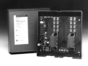
Connections are made using one standard 25-pair plug and a terminal strip. LED indicator lights display operating status. The wall-mounted unit weighs less than two pounds. The
UT-16 is FCC registered.
UT-16 Specifications
Transfer Voltage:
Minimum voltage to go from normal mode to transfer mode:
8 Vac, –10 Vdc, approximate
Minimum voltage to go from transfer mode to normal mode:
10 Vac, –18 Vdc, approximate
Number of Two-Wire Transfer Circuits:
16
Return to Normal Mode Delay Timer:
Time Interval: One to 15 minutes, selectable in
one-minute increments
Accuracy: ±10% of selected time interval
Auxiliary Relay Contact NO1:
Type: normally open (not shorted), break before make
Rating: 0.5 A maximum at 60 Vdc or 60 Vac (resistive)
Transfer Control Inputs:
Contact Input: the contact connected to the contact
input must be capable of handling 1 mA at –24 Vdc;
contact inputs on multiple UT-16 units can be bridged
(connected in parallel)
Logic Input: transfer is enabled by applying a logic low
to the logic input. Minimum logic current for logic
high: 1 mA. Input current is limited via a 1800 ohm
resistor in series with the logic input’s optical
coupler. If sufficient logic current is available, logic
inputs on multiple UT-16 units can be bridged (connected
in parallel).
Operating Modes: switch selectable for normally open
contact input, normally closed contact input, or
normally high logic input
Environment:
0 to 50 degrees C, humidity to 95% (no condensation)
FCC Registration:
Registration Number: BVV8VH-60403-PX-N
Ringer Equivalence: 0.0B
Radiated Noise Compliance:
contains no circuitry subject to EMI regulations
Reliability:
MTBF 33.3 years, per Method 1 of Bellcore TS-TSY-000332,
Issue 3, September 1990
Interconnections:
contains two 25-pair plugs and one 6-position
screw terminal strip; installer must supply two 25-pair
connectors (female)
Power Requirement:
18 to 30 Vac, 140 mA maximum
–22 to –56 Vdc, 130 mA maximum
(For AC operation use Class 2 power transformer only,
minimum 10 VA rating)
Dimensions:
8.75 inches high (22.2 cm)
8.75 inches wide (22.2 cm)
3.25 inches deep (8.3 cm)
Mounting:
wall mounts with four #8 pan-head screws
Weight:
approximately 2 pounds (0.9 kg)
Specifications
subject to change without notice.

|