|
Overview
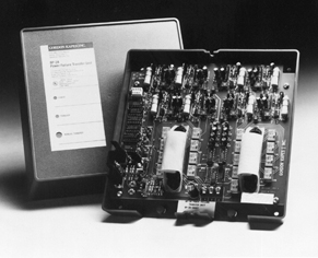
The BP-2A
Power Failure Transfer Unit is designed to connect
two-wire Central Office (CO) ground start trunk lines to
selected station telephones in the event of a power
failure or telecommunications system malfunction. The
BP-2A includes automatic loop start to ground start
conversion circuitry to provide the signaling required
to draw CO dial tone when a station telephone is brought
off-hook. This eliminates the need to add ground start
push buttons to the station telephones. In the normal,
non-transfer mode of operation, the BP-2A connects the
CO trunk lines to trunk ports on the associated PBX
system; PBX extension ports are connected to the station
telephones.
BP-2A
features include eight circuits of power failure
transfer (PFT), delay transfer on each of the PFT
circuits, LED status indicators, manual transfer switch,
an auxiliary relay contact, return to normal mode delay
timer, and universal powering. Also included are
provisions for a normally open, normally closed, or
logic level signal to control the operating mode.
BP-2A Specifications
Transfer Voltage:
Minimum voltage to go from normal mode to transfer mode: 8 Vac, –10 Vdc,
approximate
Minimum voltage to go from transfer mode to normal mode: 10 Vac, –18 Vdc,
approximate
Number of PFT Circuits: 8
Trunk Compatibility: ground start
Return to Normal Mode Delay Timer:
Time Interval: 0 to 15 minutes, selectable in 60-second increments
PFT
Circuitry Delay Transfer:
Off-Hook Recognition: 10 ±5 mA trunk loop current recognized as valid
off-hook
Off-Hook to On-Hook Duration: 1 second (nominal) break in loop current
recognized as valid on-hook
Accuracy: ±10% of selected time interval
Auxiliary Relay Contact NO1:
Type: normally open (not shorted), break before make
Rating: 0.5 A maximum at 60 Vdc or 60 Vac (resistive)
Transfer Control Inputs:
Contact Input: the contact connected to the contact input must be
capable of handling 1 mA at –24 Vdc; contact inputs on multiple BP-2A
units can be bridged (connected in parallel)
Logic Input: transfer is enabled by applying a logic low to the logic
input. Minimum logic current for logic high: 1 mA. Input current is
limited via a 1800 ohm resistor in series with the logic input’s optical
coupler. If sufficient logic current is available, logic inputs on
multiple BP-2A units can be bridged (connected in parallel).
Operating Modes: switch selectable for normally open contact input,
normally closed contact input, or normally high logic input
Environment: 0 to 50 degrees C, humidity to 95% (no condensation)
Safety Compliance: Underwriters Laboratories Inc. LISTED
Telephone Equipment
FCC
Registration:
Registration Number: BVV8VH-60403-PX-N
Ringer Equivalence: 0.1B
Radiated Noise Compliance: contains no circuitry subject to EMI
regulations
Reliability: MTBF 20.1 years, per Method 1 of Bellcore
TS-TSY-000332, Issue 3, September 1990
Interconnections: contains two 25-pair plugs and one
3-position screw terminal strip; installer must supply two 25-pair
connectors (female)
Power Requirement:
18 to 30 Vac, 140 mA maximum
Class 2 power transformer only, minimum 10 VA rating –22 to –56 Vdc, 130
mA maximum
Dimensions:
8.75 inches high (22.2 cm)
8.75 inches wide (22.2 cm)
3.25 inches deep (8.3 cm)
Mounting: wall mounts with four #8 pan-head screws
Weight: approximately 2 pounds (0.9 kg)
Specifications
subject to change without notice.

|